3D Scanner
3D Scanner
Project Overview:
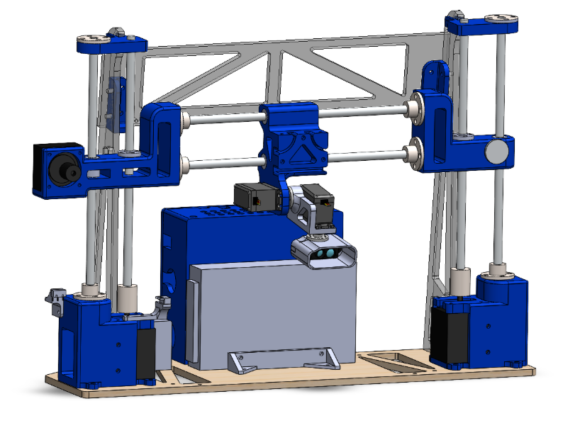
This project focuses on building a 3D scanner that captures the shape of an object and recreates it as a digital 3D plot. The system utilizes a gantry structure to move a distance sensor in a controlled pattern, taking snapshots of distances along a cartesian coordinate system. By combining the sensor’s position data with its distance readings, the system builds a digital outline of the object.
Teammate: Jacob Likins
My Role:
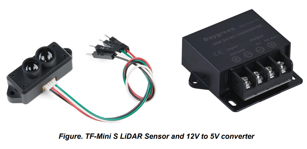
TFmini-S LiDAR sensor calibartion
Design electrical system with Arduino Nano, NEMA 17 Steppers, and DRV 8825 Stepper Controller
Design and assemble the gantry mehcanism
Sensor Calibration:
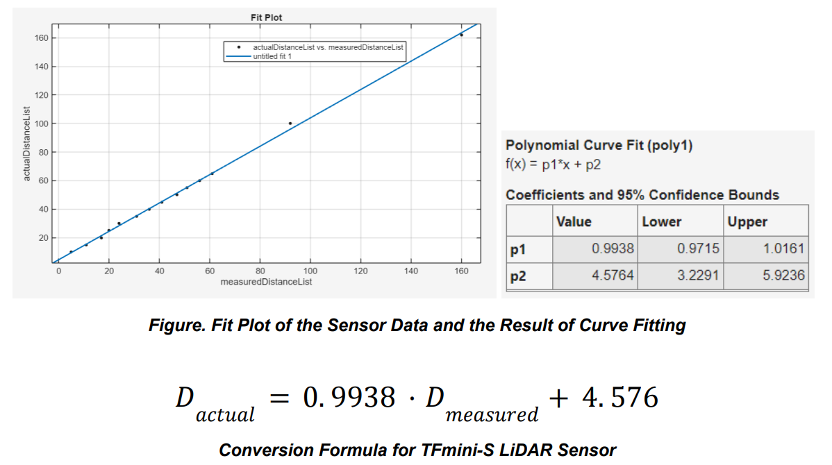
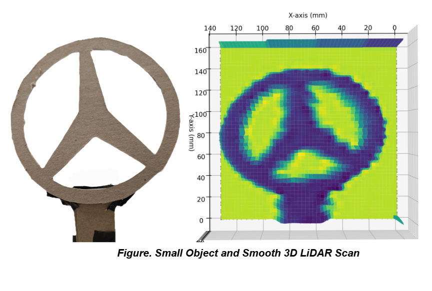
Calibration Process: We recorded 14 reference distances using a physical ruler and compared them to the sensor's raw output. Plotting this data in MATLAB revealed a linear relationship with a slight slope change at closer ranges.
Formula Derivation: Using MATLAB’s Curve Fitter tool, we derived a linear conversion
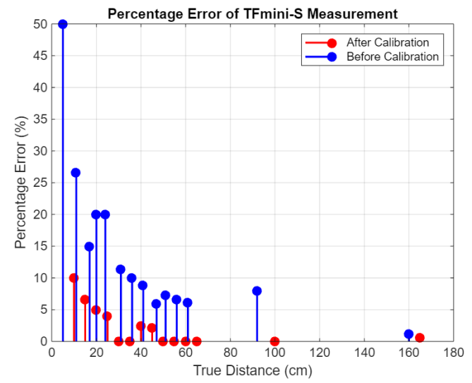
Validation: Applying this formula in the Arduino and Python scripts reduced the error significantly. In our stable operation range (>30 cm), the calibrated error is less than 3%. To maximize accuracy, we position all scanned objects approximately 30 cm away from the scanner.
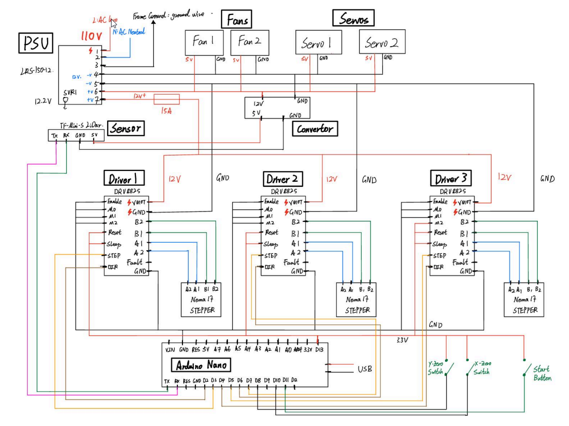
Electrical:
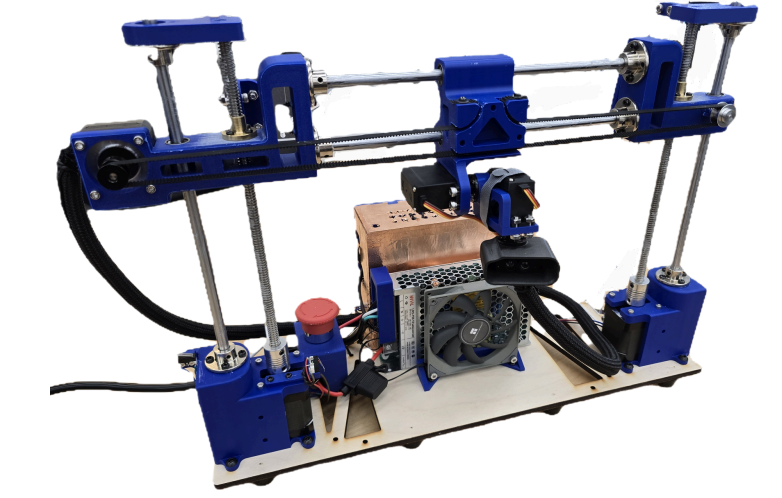
The electrical system is designed to provide stable power to high-torque motors while protecting sensitive logic components.
Power Supply: A 12V 12.5A PSU (LRS-150-12) powers the system. We integrated an Emergency Stop (E-Stop) switch in the 12V VMOT circuit to cut power to motors instantly while keeping the Arduino logic live.
Motor Drivers: Three DRV8825 drivers control the stepper motors. We added 100 µF capacitors to avoid voltage spikes and used PWM fans to cool the drivers during operation.
Controller & Communication: An Arduino Nano ESP32 manages the system. We chose the ESP32 variant specifically to handle the LiDAR's high baud rate (115200), which standard Nano boards cannot interpret accurately.
Shielding: To prevent PSU noise from interfering with data:
The electronics are stored in a PETG enclosure lined with copper foil.
The LiDAR wiring is wrapped in aluminum shielding, as the cables pass near the PSU during scanning.
Mechanical:
Gantry Design:
Y-Axis: Two NEMA 17 stepper motors drive dual 235 mm M8 lead screws, guided by M8 steel rods. This lead screw system provides small, precise increments per rotation.
X-Axis: A NEMA 17 24B stepper motor moves the sensor laterally via a 2GT belt system, operating at 1/16 microstepping.
Frame: Three acrylic frames reinforce the structure for stability.
Software Control & Motion Logic:
Homing Sequence: Upon startup, the system moves the Y and X axes until they trigger physical limit switches, establishing a known (0,0) origin.
Scanning Pattern: The scanner follows a raster pattern. It calculates a vertical step increment, completes a horizontal pass (sampling the LiDAR every 100ms), and then increments the Y-axis to begin the next line.
Key Learning:
Iterative Design & DFM: Replaced a low-accuracy servo tilt/pan mechanism with a gantry system to achieve sub-millimeter precision. This highlighted the importance of Design for Manufacturing (DFM), as 3D-printing tolerances on the guide-rod mounts initially caused mechanical resistance that required physical recalibration.
Sensor Characterization: Discovered through empirical testing that the TFmini-S LiDAR exhibits non-linear inconsistencies at close ranges (10–30 cm). Developing a linear regression model in MATLAB to correct these errors taught me how to bridge the gap between raw hardware output and reliable data.
System Integration & Modular Software: Learned the value of a modular software architecture. By developing independent blocks for LiDAR communication, stepper motor control, and data visualization, I was able to isolate and debug individual hardware failures more efficiently before final system integration.
Electrical Reliability: Gained hands-on experience in EMI mitigation and power management. Implementing copper foil shielding and decoupling capacitors was essential to preventing PSU noise from corrupting high-frequency data signals from the ESP32.